Randakk now offers GL1000 and GL1100 Float Setting gauges. Details here
I show how to set floats in the video: Randakk’s GL1000 Carb Rebuild Video

Note: The procedure for setting the float levels on GL1100 carbs is essentially the same as the one for GL1000 carbs described below. The only difference is that the float level spec for the GL1100 is 15.5 mm instead of 21.0 mm.
Setting floats on a GL1000 is relatively easy. It is a critical step in any carb overhaul. Problems with float operation affect all aspects of a bike’s performance and “drivability.” Unfortunately, the available manuals have weak descriptions of this procedure and the accompanying photos are rather poor. Worse, there is some printed material and web sites that are FLAT WRONG in the advice they give on setting floats on a GL1000. Here’s how I setup floats. My method is time-tested and bulletproof. Properly adjusted floats will stay in calibration for a very long time.
Float Theory
Floats are necessary on the carbureted engine to regulate and control the precise level of fuel in the fuel bowl. This must be done in the context of widely variable fuel usage rates.
• If the fuel level is slightly too high – a rich mixture of results. Extremely high level = flooding.
• Slightly too low – a lean mixture of results. Extremely low level = fuel starvation.
On a GL1000 the fuel flow to the carbs from the fuel tank is handled by a mechanical fuel pump that delivers fuel at about 2 psi regardless of demand.
In low demand situations (e.g., idling), excess fuel delivery by the fuel pump must be diverted to prevent flooding. Flooding in a GL1000 is serious because there are no external bowl overflow circuits. If a GL1000 carb floods, it can dump large quantities of fuel directly into that cylinder. This can lead to a minor problem (hard starting, stalling, etc.) or catastrophic engine failure (hydro-lock which can cause bent rods!).
Fuel regulation is accomplished by the rise and fall of each float. As the float rises to the appropriate level, the float pushes against a rubber-tipped float “needle” which operates against a precision machined “seat” to stop the flow of fuel. Likewise, when the float falls, the float needle opens the fuel inlet and allows fuel to flow into the bowl. In actual operation, the float needle oscillates through a relatively small range of motion. Sometimes theorists describe this motion as “vibration.” A running engine has a constant need for fuel, so the float needle is rarely 100% closed. Rather, it’s mostly regulating the flow rate of fuel into the carb bowl. Only when the engine is shut down, does 100% closure need to occur.
To protect against the possibility of float valve failure when parked, always use the petcock to shut off the flow of fuel every time you shut off the engine…that’s why it’s there. Yes, I’m well aware that the fuel tank is below the seat on GL1000s and that a mechanical fuel pump is necessary on these bikes to feed the carbs. However, the fuel pump can come to rest in a certain mode that allows fuel to flow when the tank is full or near full. At lower tank levels, siphon action can do the same!
The float needle has a spring loaded tip to allow a positive fuel seal while protecting the seal tip from too much pressure and vibration wear.
Sequence of Events
The recommended general order of carb re-assembly:
1. Reassemble the carb pairs (always keep them together throughout your rebuild!) to the plenum halves
2. Join the plenum halves (with carbs) together
3. Do the bottom of the carbs (jets, floats, etc.) As soon as the floats are set, immediately install the carb bowls
4. Do items on the side of carbs (e.g., external idle air jets and vacuum hoses)
5. Finish the top of the carbs (cap / slide assemblies)
6. Auxiliary stuff like air cutoff valve, fuel lines, etc.
This sequence is important because it protects the delicate stuff on the bottom of the carbs…like the precise setting of your floats!
Float Alignment / Prep
Prior to setting the float height, you should check each float carefully to make sure that it is square, plumb and that the pivot is true. I use a precision right angle device and lots of visual inspection. Adjust each float as necessary. This is a critical step. Unless the geometry of each float is identical, you won’t get consistent mixtures across all 4 cylinders. Poorly aligned floats can “foul” on adjacent structures and cause chronic fuel starvation or flooding. I take an additional step …I weigh all four floats to make sure they are evenly matched. On my scale, clean floats weigh 12 grams. I throw out any outliers than vary by more than 1 gram. The synthetic floats used on GL1000s aren’t prone to saturation like old-fashioned brass floats, but weight-matching is a good idea nonetheless.
Below are some pictures which show pairs of floats. The float on the left in each pair is a perfectly aligned float. Each of the floats on the right has an alignment problem. The problems have been exaggerated for clarity. When you finish this inspection / alignment, your float should be square (parallel or perpendicular) in every plane relative to the carb body. Be very careful when bending your floats into alignment. They are rather fragile and are easily damaged.


Also, you should clean and ream the float pivot holes (on the float). Don’t remove excess amounts of metal or you will corrupt the geometry of the float pivot-to-float pin relationship.
Likewise, verify that there is no binding on the float pivot pins where they insert into the posts in the carb body. Polish the pins with crocus cloth and ream the posts as necessary to get a snug but free fit. When correct, you should be able to insert the float pivot pins with fingertip pressure only. Again, don’t remove excess amounts of metal.
Float Setting
The correct spec is 21 mm. This is measured from the bottom edge of the float to the raised lip adjacent to the carb body fuel bowl gasket surface. An important point of clarification: “bottom” edge is defined as oriented when installed on the bike. Remember this fact when your carbs are upside-down or tilted up on their end on your bench.
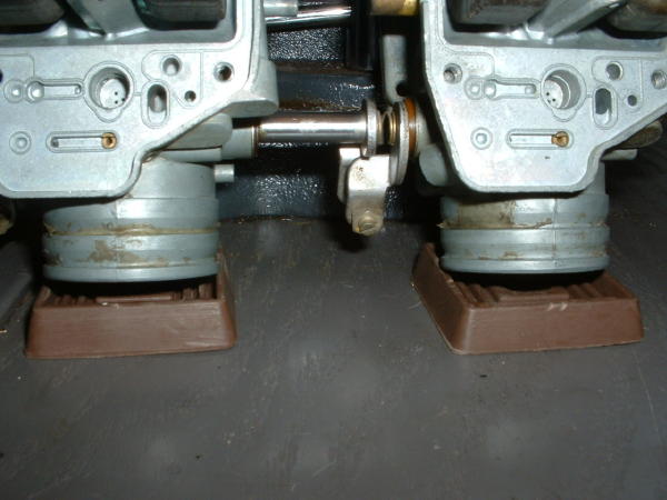
When you take your measurement, be sure the spring loaded “tip” of the float valve is contacted but not depressed. The best way to accomplish this is to set the rack up (on end) on your bench and tilt it slightly away from vertical so that it rests against something sturdy (I use my bench vise). Then measure the floats on the lower pair of carbs. Important – the float you are measuring must be hanging from its float pivot pin. Here’s how I place the carbs on my bench to measure and set floats. Notice the two rubber furniture coasters I use to keep the rack steady:


Some manuals repeat the generic advice to measure “from the gasket surface.” This is vague and misleading in the case of the GL1000. Here are two pictures showing where and how to measure GL1000 floats. Notice that the gasket is in place for these photos! Notice also that my float gauge is clearly resting on the raised lip rather than the gasket surface. Measuring from the gasket surface will produce float settings that are too high and result in an over-rich condition!
Correctly set floats will be parallel to the main carb body flange along the entire length of the float edge.
I have a variety of shop-grade precision tools that I can use to measure and set float heights. Each of the measuring tools below is set to measure 21 mm. I usually reach for the 69 cent item shown in the picture below sourced from Ace Hardware. You don’t need anything fancier to get excellent results. Be sure to measure both sides of the float!


Randakk’s GL1000 and GL1100 Float Setting Gauges
As shown above, I now offer my own gauges for checking / setting floats on GL1000 and GL1100 carbs.
The adjustment should be done at the “tang” that contacts the float needle. You will see some instruction elsewhere and in some manuals advising that you adjust the float level by bending the float arms…NOT!!! My view is that bending the 2 arms of the float instead of the single tang is lunacy. Bending the arms introduces all sorts of unnecessary geometric distortion of the float. The accepted practice for generations across dozens and dozens of carb manufacturers has always been to adjust float level at the “tang.” My theory is that this “arm bending” idea crept into the picture from some sloppy translation and technical writing work from the original Japanese text. Believe me, the engineers at Keihin intended for the float height adjustment to be made at the tang.
Here’s a photo below showing the “tang” where the float height adjustment is made.

Adjust the “tang” as necessary to get the measurement to exactly 21 mm. Also, when the measurement is correctly set, the bottom edge of the float should be exactly parallel to the carb body along the entire length of the float…not just at one point of measurement. When satisfied with the first pair, flip the carbs over and repeat for the other two.
Note:
In addition to the above details, correctly set floats should have a “gap” of about 2 mm under the float “tang” relative to the surrounding float arm architecture. I can usually take this fact and eyeball float levels to within 1 mm of perfect before I even begin to measure.
Caution:
There is also another tab on the float which limits downward movement. This “down stop” tab rarely requires adjustment. Unfortunately, sometimes folks get confused and think this is the “tang” where you adjust to set float height. Unbelievably, I recently had a professional motorcycle mechanic correspond with me about problems he was having setting float height on a GL1000. Turns out he was trying to make the float height adjustment at the “down stop” tab. It’s purpose if to prevent the float from “fouling” when in the fully down position.
If you mess with these, it’s possible that the floats might not be able to “drop” to allow fuel to enter the bowl. In fact, this can result in a high speed fuel starvation and over-lean condition. In extreme cases, this can cause your bike to overheat to the point that the exhaust manifolds will turn cherry red! Properly adjusted down stop tabs will permit the float’s forward edge to drop about 1/4″ from the fully up position (as installed on the bike). This should coincide with the bottom edge of the float dropping to a parallel position with the bottom of the main jet towers when the float is in the full “down” position. (Remember, if your carbs are upside-down on your bench the direction of movement direction is reversed).
Adjustment of the down stop tab is not nearly so critical as float height. So long as the down stop tab will permit the float to drop when the fuel level drops and stops the float before it contacts the bottom of the float bowl, you will be fine.
Below is a picture of the Down Stop Tab. This is NOT used to set float height!

FINAL CAUTION:
Make sure the float needle clip doesn’t bottom out and contact the float seat. This can happen on some aftermarket float sets because the needles are not long enough or the seats are too deep. In my own work, I always use OEM Honda float sets to avoid the disappointing quality issues with aftermarket float needle sets.
Note: The procedure for setting the float levels on GL1100 carbs is essentially the same as the one for GL1000 carbs described above. The only difference is that the float level spec for the GL1100 is 15.5 mm instead of 21.0 mm.
Key Links:
- https://www.randakks.com/randakks-honda-gl1000-gl1100-cam-belt-cover-tool.html
- https://www.randakks.com/randakks-honda-gl1100-float-setting-gauge.html
- https://www.randakks.com/randakk-s-maintenance-area/randakks-tools/honda-gl1000-float-setting-gauge.html
- Randakk’s GL1000 Carb Rebuild Video
If you want to find the best selection online for motorcycle parts, visit our stores below:
www.DimeCityCycles.com | www.Z1Enterprises.com | www.Randakks.com | www.MikesXS.net


First great site best out there, giving good info at every turns. So my question: the tang on teh float before setting the float into position a setting it. What should the position of the tang be in relation to the whole bracket. I have seen the tang bent/curved, push way down?? Should it be straight and level with the bracket and if not what position should be tang be relative to the bracket it is part of; seems like how it sits relative to the bracket could/will effect the setting measurement substantially???
Great website and thank you for excellent describing how to set the float with every single detail, that is awesome my friend and very useful for someone knows what is doing, many thanks and kindle regards,
1975 &1976 GL 1000
i just wanna say THANK YOU! For your pristine and unselfish advive and time you have put in to this site! thank you very much I bwiil point anyone one and every1 I can to your site sir ! THANKS AGAIN!!
Kind regards
Rick
86 GL1200 19K Sat 3 yrs ooof such a gummy mess
Hi. Regarding the float valve needle on the GL1000, if you depress the little piston on top of it should it slowly return to the upper position of should it spring back quickly?
Should return quickly if clean and not worn.
I have a question, I hope you can help with. I’ve rebuilt the carbs per good sense, experience and close attention to the directions on your site. When I fire the bike up, it runs for a few seconds and then fuel starts leaking out of the carbs and running down onto the top of the engine. Hard to tell exactly where it is leaking/overflowing from but I’ve had the carbs apart twice now in the search for what I thought was a stuck float. I’m now thinking that whatever mechanism is in place to stop overpressure form the pump isn’t working. If I turn the petcock off the overflowing doesn’t happen and the bike runs, until the bowls empty.
Any ideas on the pump situation?
Thanks
Dean
Not a fuel pump pressure issue. It is constant at 2.5 psi max. (unless you have an incorrectly-sized electric fuel pump fitted.)
Here are the common causes of flooding: http://www.randakksblog.com/flooding-issues-on-vintage-hondas/
Most likely your trouble is on that list.
Hi! Im rebuilding my -78 carbs and I like to know the heigt of the level in the cups.
mesure from the machined surfase and down. I have done all the adjusments as in your blog but it differs and I dont know what is right. MVH Kaj Lind from Sweden.
Sorry. Your question is not entirely clear. GL1000 float height is not measured from the machined surface per normal practice.
Use the method shown to measure from the ‘raised lip.” The float height spec is 21mm measured as we show. Any other method is incorrect. Our video also shows this in great detail.
There’s not much really to say except that what’s in the above document has been a tremendous help in understanding and fixing the problems I been going through in setting my floats. The above is the clearest instruction and is backed up with photographs which give a better understanding what you need to do. To do it correctly.
I loved the video, the main actor was great. Is there a way that those of us that bought the DVD and rebuild kit could get a thumb drive version from you? Yes or no, still loved the production values.