Welcome to a new world of off-road adventures brought to you by Randakks Cycle Shakk, where we explore the Honda CRF series – a marvel in the off-road motorcycle industry. As experts in the Goldwing community, we’re branching out to share insights into a range that has revolutionized off-road riding.
The Honda CRF Series: Trailblazing Excellence
Explore the Honda CRF series, a lineage celebrated for performance, innovation, and pure excitement.
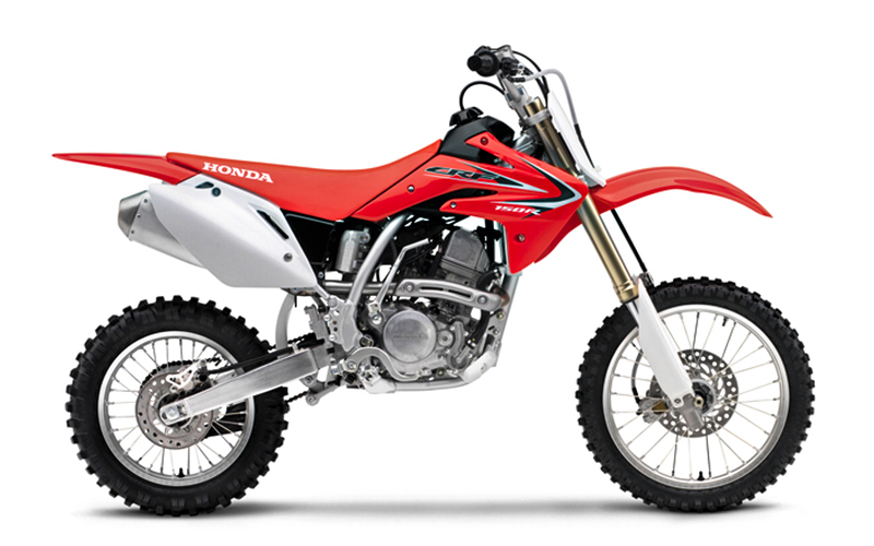
Honda CRF150R: Entry-Level Off-Road Brilliance
The Honda CRF150R is an embodiment of the passion and innovation that Honda puts into their off-road machines. Crafted to provide entry-level riders with a smooth initiation into the world of dirt biking, this bike is laden with features that make it stand out in the crowded youth segment. Let’s take an in-depth look at what makes the CRF150R a favorite among aspiring riders.
Engine: Liquid-cooled single-cylinder four-stroke
The heart of the CRF150R is its 149cc liquid-cooled, single-cylinder four-stroke engine. This configuration is designed to provide a smooth yet powerful riding experience.
- Liquid-Cooling System: This technology ensures that the engine maintains optimal temperatures during demanding rides. The liquid-cooling not only adds to the durability of the engine but also aids in delivering consistent power output.
- Four-Stroke Configuration: Unlike two-stroke engines commonly found in smaller bikes, the four-stroke engine offers better fuel efficiency and a more linear power curve. This makes it more manageable for younger riders while still packing enough punch to excite.
Displacement: 149cc
The 149cc displacement is a perfect middle-ground for young riders, allowing them to feel the thrill of a high-performance engine without being overwhelmed.
- Power Output: This engine configuration provides an exciting yet manageable power range that’s appropriate for beginner and intermediate riders. It strikes a balance between being approachable for new riders and offering room to grow.
- Efficiency and Performance: Honda’s engineering ensures that the 149cc engine delivers a responsive and lively ride without compromising on fuel efficiency.
Chassis and Suspension
The Honda CRF150R is not just about the engine; its chassis and suspension are designed for top-notch handling and comfort.
- Lightweight Frame: The bike’s frame is crafted to offer a robust yet lightweight structure, enhancing the bike’s agility and responsiveness.
- Advanced Suspension System: The front and rear suspension systems offer versatile adjustability, ensuring optimal performance across diverse terrains and catering to individual rider preferences.
- Braking System: Equipped with disc brakes on both the front and rear, the CRF150R offers excellent stopping power, boosting rider confidence.
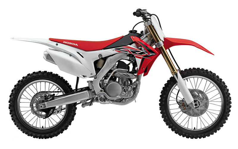
Honda CRF250 Series: Power and Versatility on Trails
The Honda CRF250 Series is a testament to Honda’s dedication to excellence in the world of off-road biking. Comprising models like the CRF250R, CRF250X, and CRF250L, this series offers a versatile range of off-road bikes tailored for racing, trail riding, and even dual-sport use. Let’s explore the intricacies of the CRF250 Series that make it an outstanding choice for riders seeking power, agility, and adaptability.
Engine: Liquid-cooled single-cylinder four-stroke
The liquid-cooled, single-cylinder, four-stroke engine is the foundation of the CRF250 series, providing a high-revving and responsive performance across the range.
- Liquid-Cooling System: Designed to maintain consistent engine temperatures, the liquid-cooling system contributes to a sustained power output, even under extreme riding conditions. It ensures the longevity of engine components and provides reliability.
- Four-Stroke Design: The four-stroke configuration emphasizes torque and control, lending to a more tractable power delivery that suits various riding styles and terrains.
Displacement: 249cc
The 249cc displacement of the engine in the CRF250 Series offers riders a thrilling and potent ride.
- Power and Efficiency: A 249cc engine packs a strong punch in terms of power but remains efficient and rider-friendly. It provides the energy for aggressive trail riding and racing, yet can be harnessed comfortably by riders with different skill levels.
- Versatility Across Models: This displacement works across different models in the series, enabling a uniform yet distinct experience for riders whether they choose the CRF250R for racing, the CRF250X for trails, or the CRF250L for dual-sport purposes.
Distinct Models: CRF250R, CRF250X, CRF250L
Each model in the series caters to unique riding needs, yet they all share the core of the CRF250 philosophy.
CRF250R: The Racer’s Choice
- Performance-Oriented: Designed with motocross racing in mind, the CRF250R offers aggressive tuning, a performance exhaust system, and a lightweight chassis.
- High-Revving Engine: The engine’s ability to rev high complements the racing DNA of this bike, offering thrilling acceleration and sharp responses.
CRF250X: Tailored for Trails
- Trail-Ready Suspension: The CRF250X comes with a softer suspension setup that provides comfort and control on rugged trails.
- Versatile Power Delivery: Its engine is tuned for a broader torque spread, providing power when needed, without sacrificing the ability to traverse challenging terrain.
CRF250L: Dual-Sport Capability
- Street and Trail Balanced: The CRF250L bridges the gap between on-road commuting and off-road adventure, with a balanced engine tune, comfortable ergonomics, and necessary street-legal features.
- Adventure Ready: It’s a bike that can take on city streets and country trails with equal poise, emphasizing Honda’s commitment to versatility.
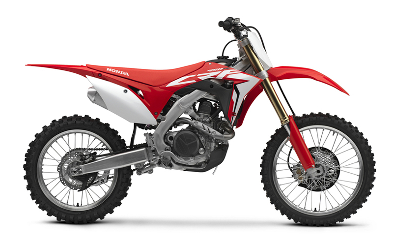
Honda CRF450 Series: Dominance in Off-Road Racing
The Honda CRF450 Series stands as a symbol of off-road excellence, bringing together raw power, precision engineering, and innovative design. Comprising models like the CRF450R, CRF450X, and CRF450L, this series has become a go-to choice for professional riders and enthusiasts alike, each model catering to specific off-road biking needs. Here’s an in-depth exploration of the features and performance characteristics that make the CRF450 Series a dominant force in the off-road racing world.
Engine: Liquid-cooled single-cylinder four-stroke
The CRF450’s engine is a remarkable feat of engineering that sets the tone for the bike’s performance across all terrains.
- Liquid-Cooling System: Essential for maintaining optimal engine temperature during high-intensity rides, the liquid-cooling system ensures consistent performance while mitigating wear and tear.
- Four-Stroke Configuration: The four-stroke engine delivers a steady flow of power, producing an effective torque curve that makes handling more predictable and engaging.
Displacement: 449cc
At 449cc, the engine displacement offers an incredible blend of power and agility, suitable for both competitive racing and recreational off-roading.
- High Power Output: With 449cc, the CRF450 series boasts an engine that has a thrilling output, capable of propelling riders to remarkable speeds and conquering demanding terrains.
- Performance Tuning Options: This displacement allows riders to fine-tune the engine’s performance to suit individual riding styles and track or trail requirements.
Distinguished Models: CRF450R, CRF450X, CRF450L
Each model in the series has been carefully engineered to meet specific demands and preferences of different off-road riding disciplines.
CRF450R: The Racing Behemoth
- Track-Focused Design: With sharp handling, lightweight construction, and aggressive power delivery, the CRF450R is crafted for competitive racing.
- Advanced Suspension System: A competition-oriented suspension setup enhances the CRF450R’s agility and responsiveness on the race track.
CRF450X: The Trail Master
- Versatile Performance: The CRF450X is designed to tackle everything from tight trails to open desert terrains, offering a balanced engine character and suspension tuning.
- Robust Construction: Built to endure, the CRF450X boasts a rugged frame and durable components, making it a reliable partner for long trail rides.
CRF450L: Dual-Sport Excellence
- On-Road and Off-Road Capability: Bridging the gap between trail and tarmac, the CRF450L provides a blend of off-road prowess and on-road legality.
- Adventurous Design: With features that cater to long-haul exploration, the CRF450L is a trustworthy companion for those who seek adventure beyond the traditional off-road paths.

At Randakks Cycle Shakk, our recognition for quality and innovation extends far beyond our esteemed Goldwing parts and accessories. The Honda CRF series stands as a testament to dedication, engineering prowess, and the unbridled passion that fuels the heart of every motorcycling enthusiast.
With the CRF series, riders of all levels find a gateway to exploration, excitement, and excellence. From the entry-level off-road brilliance of the CRF150R to the adventurous trails with the CRF250 and CRF450 series, Honda’s lineup embodies a diverse and thrilling world of off-road biking.
Whether you’re seeking raw power, versatile performance, or environmentally responsible riding, the Honda CRF series offers a spectrum of choices tailored to your unique passion and pursuits. Our commitment at Randakks Cycle Shakk is to not only provide parts but to also engage, inspire, and support your journey.
Join us at Randakks Cycle Shakk to delve deeper into the Honda CRF models, explore the exhilarating world of off-road racing, or embark on unforgettable motorcycle adventures. Together, we celebrate the spirit of innovation, adventure, and the timeless joy of riding that Honda’s CRF series brings to life. Come experience the future of biking, grounded in tradition and propelled by excellence. Your trail awaits.
SELECT YOUR CRF MODEL TO SEARCH FOR PARTS ON RANDAKKS
This blog post is brought to you by Randakks Cycle Shakk, a hub for Goldwing enthusiasts and anyone passionate about motorcycles. Stay tuned for more insights into the world of two-wheeled wonders, and as always, ride with pride.