For the static timing light needed for this procedure Click here
Robert Overby wrote a very interesting article titled “Improving Your GL1000’s Performance” which appeared in Wing World in the June 1995 issue. You can find this article by searching the GWRRA Message Board Archives (see my links page). This is a GREAT article that explains some weird design problems unique to the GL1000 ignition system as well as methods to resolve them. I guess I’m a bit of a contrarian, but I like breaker point ignition systems. In my opinion, no one needs to resort to an electronic ignition system to have a decently tuned GL1000.
If you blithely set the breaker point gap and static timing “by the book” without consideration of Robert’s revelation, you will most likely introduce 2 unintended (bad) consequences. I give full credit to Robert for solving these mysteries.
I’ll try not to go into a deep technical explanation (read Robert’s article!), but I will summarize what you need to do to get great results. First, you need to understand that the GL1000 relies on a “wasted spark” system in which each coil fires 2 plugs simultaneously…one on the compression stroke (working spark) and one on the exhaust stroke (wasted spark). This is why you have only 2 breaker cam lobes firing 4 spark plugs. There’s nothing wrong with this system in theory or practice. Many other motorcycles use this design without a problem. The engineering advantage is that it reduces the number of parts required, eliminates potential points of failure, and saves weight (you only need 2 coils instead of 4).
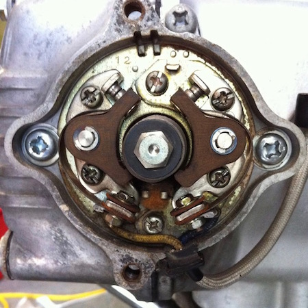
The breaker cam / advance mechanism is mounted onto the end of the left camshaft. Here’s the first unexpected problem – the left camshaft is adequately supported by its bearing surfaces in the left head to do its main job of opening and closing the valves. However, the bearing support does not prevent the aft end of the cam (where the breaker points are) from “walking” around in a slight wobble. This effect is caused by camshaft flex induced by valve spring pressure. This anomaly is just enough to disturb ignition timing. The good news is that it (usually) only affects the timing of cylinder #1 and #2.
Wear or “slop” in the eccentric that operates the points can make the problem worse. Ditto for problems with the ignition advancer.
Here’s how to judge: 5 degrees of timing equals about 7/16″ inch on the flywheel …5 degrees is also the distance between the “F” and “T” marks (this is the value on ’75-77 models. Later ’78-’79 models have 10 degrees between the “F” and “T” marks).
Move the base plate so that you “split the difference”…one cylinder will be a little early and one will be a little late. You don’t really need to keep track of which cylinder is early or late, just make certain that the “early” cylinder never fires more than 2 degrees before the F mark. If you just go “by the book” and don’t follow the procedure described above, you can end up with 1 cylinder up to 5 degrees earlier than the F mark. This causes the low speed to knock off the front of the engine many GL1000’s exhibit. It’s hard to recognize because it’s actually a “spark knock” of an engine under no load, but only affecting 1 out of 4 cylinders. “Splitting the difference” is not a perfect solution, but it gives you an acceptable compromise with much smoother idle manners.
When you’re done, set the timing for #3 and #4 relative to the F mark for “2” on the flywheel by moving the points sub-base (there shouldn’t be any appreciable difference induced by “wobble” on this set).
Here’s the second problem you can have, even when you carefully follow the workshop manual. The spec for the breaker point gap is listed as 0.012″ – 0.016.” Without coaching, most people will aim for the middle (0.014″) as a hedge against their less than expert skill with a feeler gauge. Again, I’ll skip the theory, but if your point gap is on the smaller end of this range you can end up with a problem called “dwell overlap.” Dwell is defined as the duration of time that the points are closed and the primary winding of the coil is energized.
Basically, you want to make sure that you never have both sets of points closed at the same time. If you do, the non-isolated nature of this design will allow a voltage drop that can dissipate the saturation of the second coil and cause a weak, unreliable spark.
Don’t worry about electrical engineering theory. Here’s what you do. Aim for the “high” end and set the breaker gap at 0.016″. Next set the timing per the special instructions above. Then using your test light, ohmmeter or buzz box rotate the engine through several revolutions (for each set of points). As detailed above, the points for #1 and #2 should OPEN at +/- the F mark for “1” on the flywheel. Now make an additional check to determine that they do not CLOSE until AFTER the F mark for “2.” If they close early, you need a more point gap which results in less dwell. Each increase of 0.001″ point gap reduces dwell by about 4 degrees. Note, each time you adjust the point gap, you MUST reset the timing!
Once you’re happy with #1 and #2, repeat the procedure with #3 and #4. In this case, the points for #3 and #4 should OPEN exactly at the F mark for “2” on the flywheel AND they should not CLOSE until AFTER the F mark for “1.
“ This all sounds complicated and I’ve described it in several steps and in more detail than I intended. In practice, it’s quite simple. Here’s all you need to do in a step-by-step summarized sequence:
1. Set the point gap for #1 and #2 at the max. end of the range (0.016″)
2. Set the timing for #1 and #2 using the “split the difference” method relative to the F mark for “1”…early cylinder no more than 2 degrees before F mark for “1”
3. Check that points for #1 and #2 CLOSE after the F mark for “2”…if not increase gap, re-time and repeat this test
4. Set the point gap for #3 and #4 at the max end of the range (0.016″)
5. Set the timing for #3 and #4 relative to the F mark for “2”
6. Check that points for #3 and #4 CLOSE after the F mark for “1”…if not increase gap, re-time and repeat this test
Once you get everything set correctly, minor maintenance is reduced to periodic cleaning and re-gapping of the points to the max. value. You don’t have to futz with timing every time.
Point of clarification which confuses some people: The “1” and “2” marks on the flywheel do not refer to cylinder 1 and cylinder 2. Rather the “1” on the flywheel [and it’s associated T (Top Dead Center), F (static ignition fire), and Full Advance marks] refer to all of these events for both cylinder 1 AND 2 and the associated set of ignition points for cylinders 1 and 2. The events are phased 360 degrees apart.
Likewise, the “2” on the flywheel [and it’s associated T (Top Dead Center), F (static ignition fire), and Full Advance marks] refer to all of these events for both cylinder 3 AND 4 and the associated set of ignition points for cylinders 3 and 4.
Odd observation. I’ve worked on a few bikes that had the timing variation on cylinder #3 and #4 instead of the expected timing variation on cylinder #1 and #2. I have no explanation for this. The cure was the same…split the difference in timing on #3 and #4 with the early cylinder no more the 2 degrees before the “F” mark.
Tip: Be aware that there are 2 ways to hook up your static test light. The light will go “on” or “off” at “F” depending on the method you use. Either method is fine. I use the light “on” at “F” (light comes on as points open). This requires that the ignition switch and kill switch are both set to on.
Another Tip: Contrary to some manuals, ignore the punch mark(s) on the eccentric breaker cam when setting points gap. They were not created very precisely by the factory and amount to an unnecessary distraction. Just aim for the highest point on the cam lobes and then set the points.
Yet Another Tip: To avoid the unnecessary distraction of a test lamp that alternates between bright, dim and off-put a small piece of paper (like a section of a business card) between the points on the side you are not adjusting. This will allow your test lamp to have only 2 modes: bright and off. Without this step, the activation of the “other” coil will make your test lamp dim in a distracting fashion.
Final Tip: The aftermarket Dyna/S electronic ignition conversion is triggered off the end of the left cam and retains the OEM spark advancer. Dyna/S equipped bikes typically exhibit the same “wobble” as bikes with breaker points. The cure is the same: “split the difference.”
Key notes:
- https://www.randakks.com/catalog/product/view/id/5599/s/dyna-s-ignition-ds1-3-gl1000/
- https://www.randakks.com/randakks-honda-gl1000-static-timing-light.html
If you want to find the best selection online for motorcycle parts, visit our stores below:
www.DimeCityCycles.com | www.Z1Enterprises.com | www.Randakks.com | www.MikesXS.net


I purchased a 1977 GL1000 about two years ago as a project bike. This summer, I decided to replace the timing belts because I had no clue when the prior owner replaced the timing belts. I also checked the timing based on recommendations and re-synchronized the carburetors. Based on comments on the Goldwing websites, I decided to purchase the Randakk degree wheel to check the timing. I found the Randakk degree wheel and the instructions to be a big help and produced excellent results.
The information in the timing wheel’s documentation comparing the timing between cylinders for each set of points and cam wobble was helpful. I found the advance between cylinders 1/3 was over 5 degrees different, and cylinders 2/4 was over 10 degrees. Therefore, the split timing process suggested in the documentation provided a big help in improving how smoothly the motor idles and accelerates.
I spent a couple of weeks experimenting with several combinations and found the following:
1) I found my old 1975 Sun timing light and performed static and dynamic timing. During dynamic timing, the advance did not seem to move very smoothly. Therefore the centrifugal advance was removed and cleaned based on a Randakk blog recommendation. I found that cleaning the centrifugal advance improved the smoothness of the spark advance.
2) After a couple of weeks of experimenting, I found setting the advance at the maximum suggested setting of 7 degrees for each set of points and a .016 ignition point gap works well.
3) The motor idles and runs much smoother now, and little low-speed stumble. The bike starts better, and I do not downshift going slow as much. On my test route, the gas mileage has improved by about 2 or 3 miles per gallon, to 42 or 43 miles per gallon.
Bottom line, I feel the money spent on the degree wheel and the documentation provided a big bang for the buck, and it seems like I have a different bike now. Previously, I was thinking about purchasing electronic ignition and coils, and I do not plan to buy them now.
Thanks a lot for this top valuable information. Have You seen a case when You have had to split the timing for both banks?. I followed steo by step your instructions, #1 advanced 2 degrees, #2 retarded 3,5. But #3 and 4 had to be split too !!! #3 advanced 3 degrees and #4 retarded 4,5 (almost at T mark). I understand You mentioned to not advance a cilinder more than 2 degrees, but is good to have a point opening after its T mark?
I did the gap adjustment for avoiding bot points closed at the same time, but didn’t test the bike on, task for tomorrow. Any advice would be appreciated. Thanks in advanced
This reading has been a master class for me, thanks a lot for sharing this kind and level of information. Greetings from Venezuela
First of all, thanks a lot for your article on ignition quirks, that is a perfect guide for a rookie like me… It should hoppefully help me to makes the proper tuning that my recently bought 77′ GL 1000 deserves. Yet, to be sure to proceed correctly, may you please answer a question concerning step 3 (“Check that points for #1 and #2 CLOSE after the F mark for “2”…if not increase gap, re-time and repeat this test”) : Do i have to make this check for both cylinders 1 and 2 ? I explain… I am in a situation where the timing has been (in my opinion) properly set for cylinders 1 and 2 (early cylinder ~2° before F mark for “1”, and late cylinder ~2° after), however when checking the closure of the points, it appears that for the early cylinder the points actually close after the F mark for “2”, but for the late cylinder, they close before ! Does this mean that i have to enlarge the gap between the points for #1 and #2 ?
Thank a lot in advance for your help !
Hi
I am rebuilding a 1975 USA import Gold Wing here in Sydney. The engine has had a hard life and I need to do a lot of work to get it running well.
I want to change the points for an electronic system – Dyna/S ?? can I order one from you guys or can you tell me where I can get one.
Thanks
Available here ever day: https://www.randakks.com/catalog/product/view/id/5599/s/dyna-s-ignition-ds1-3-gl1000/category/597/
Installation tips here: http://www.randakksblog.com/dynas-installation-troubleshooting-on-the-honda-gl1000/
Thanks.
Thanks guys this will be the first of a long list of issues I think.
Dave M
Hi, I`m new at this and was wondering where do i find a form/site on how to change from points 76 GL1000 to electronic ignition.. I put in a Dyna Tek from a 77 GL1000 and went to start it and all it does is turns over and backfires? Is there a check list of what all i was suppose to take from the other bike to make mine work?? All the help will be appreciated . Do i do the timing with a meter and which/where do you point the probs….HELP..
The best tech advice can be found on this Forum: http://www.ngwclub.com/forum/
See also on this BLOG/Tech:
http://www.randakksblog.com/dynas-installation-troubleshooting-on-the-honda-gl1000/
http://www.randakksblog.com/ignition-quirks-split-timing-technique/
Yo! That “final tip” was a killer for me… I obsessed and obsessed over wierd behavior of my LED timing light until I remembered this final “note”. Now everything is perfect!
Glad you got it sorted! Randakk
that last 0ne was good…I was having the bright-dim-off thing myself and thought maybe it was the LED static light I”d made up….also had no idea about the overlap affecting the coils in that way, I”m hoping this cures my ignition woes….thanks