This Tech Tip is provided courtesy of Ray Proebstl of Munich, Bavaria, South Germany. Ray is a professional educator in the field of electronics. He is a long-time avid GoldWing enthusiast.
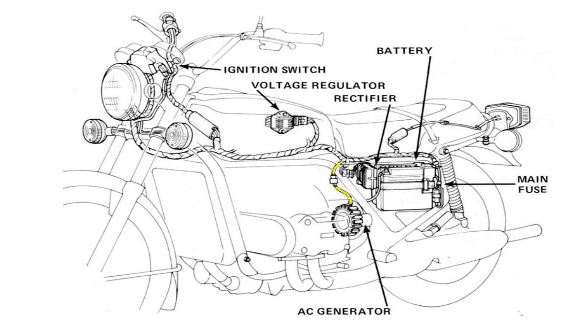
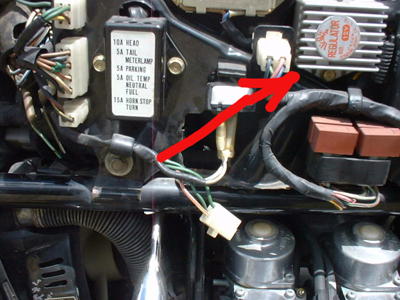
Here are the components of the GL1000 charging system.
Typical Problems:
- Undercharging: the battery is only partially charged and starting the bike after a week or two is impossible, the starter won’t spin.
- Overcharging: battery electrolyte is “boiled” dry and electronic components fail.
Battery Theory:
A lead-acid cell has a typical voltage of 2 Volts (without load). Depending on how it is charged, the voltage goes from 1.8V (deep discharge) to 2.4V (fully charged). Like almost any automotive battery, the GoldWing battery has 6 cells, typical voltage 12V. A good charging system supplies a maximal voltage of 14.4 Volts (6 x 2.4 V). If you charge a battery with 14.4V, the charging process automatically stops, when the battery has also reached 14.4V. If you charge it with a higher voltage, the battery fluid will be electrically divided into hydrogen and oxygen, coming up as bubbles and leaving through the breather tube. This gas mixture is highly explosive! Finally, when all the fluid is gone, the battery is dry, with only acid residue remaining in the cells. That is why you must not add acid only when the battery fluid level is low, but only distilled water!
This means: you cannot effectively charge a battery with a voltage less than 12V or higher than 14.4V.
Testing the Battery:
Go to a garage or shop where they sell automotive batteries, they usually have special devices (load testers) to check the battery. It is not possible to make reliable tests with a normal gauge/multimeter.
Alternator Theory:
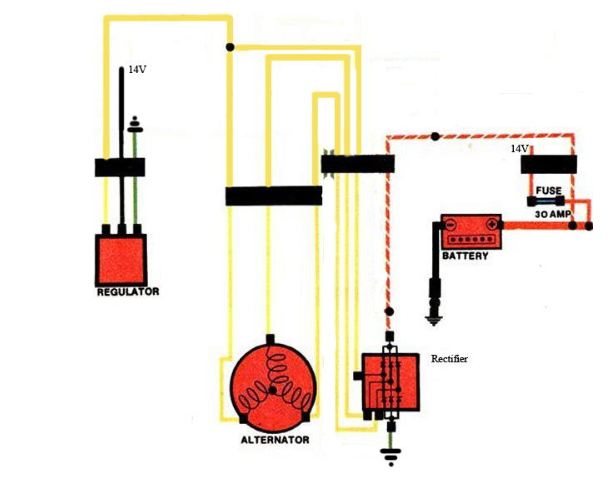
The GL1000s have a 3-phase-AC-generator located on the left side of the engine above the clutch in the rear engine cover. The alternator is maintenance-free, You would have to pull the engine to get access to it. It consists of a stator with 18 coils and a rotor with six magnets. The eighteen coils on the stator are actually only three coils, each divided into six parts. In wiring diagrams, the three-phase generator is therefore shown with three coils only. They are connected to form a Y, the ends of the Y are the yellow wires coming out from the rear engine cover.
I call them A, B and C, but they are electrically equivalent. These stator coils are isolated and not connected to the ground.
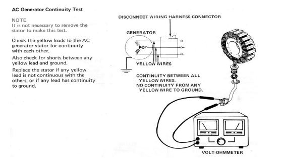
Testing the stator coils for continuity:
- Unplug the 3-wire stator connector.
- Using a normal ohm gauge or multimeter, set it to measure small resistances (lowest ohm range)
- Check the resistance between:
- wire A and B
- wire B and C
- Wire C and A
- You should always have about the same reading, which is typically between 1 and 2 Ohms.
- Any resistance value greater than this on any of the wire pairs means that phase has failed and the stator must be replaced.
Testing the stator coils for ground faults:
- Switch to a high ohm range on your multimeter and check the insulation of the coils by measuring the resistance between A and ground, B and ground, then C and ground.
- Use a reliable ground point such as the rear engine cover.
- You should get infinite resistance (no path to ground).
If both continuity and ground tests are satisfactory, your stator is healthy.
Rotor theory:
A rotating magneto field creates AC voltage in the stator coils. The stronger the magnetic field, the higher the voltage. The faster the rotation, the higher the voltage. The GoldWing rotor has six permanent magnets and is connected to the crankshaft by a chain. That means: The output voltage of the stator is low at idle and maximal at 8000 RPMs, because the magnetic field cannot be controlled and is always constant. (Automotive alternators have a rotor with a so-called field coil, which is nothing else but a magnet with variable strength. Automotive alternators reduce the magnetic field in the rotor with rising rpm, therefore the output voltage is constant.)
Testing the rotor is not practical. The rotor magnets may have become weak by age, vibration and heat. Measuring the magnetic field is very complicated. You can test the magnets indirectly by measuring the output voltage they create in the stator. More about this method later.
Charging system:
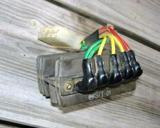
It consists of a 3-phase rectifier unit located to the left of the battery:
…and a regulator unit under the left “false tank” half:
The rectifier unit transforms 3-phase AC to DC with the help of six diodes. With the stator producing various voltages, depending on engine rpm, the DC coming out of the rectifier is also not constant. It can go up to 100V at 8000 RPMs! What can be done now? Honda engineers found a very simple but primitive method: They installed a regulator unit, which drains current from the stator coils when the voltage gets too high, thus causing the voltage to drop (a “shunt” regulator).
Testing the charging system:
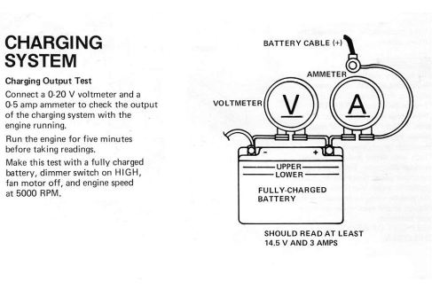
Attach a DC voltmeter to the battery terminal while the engine is running. (Or use the DC 20V range of your multimeter). The battery voltage should not drop below 12V when idling and should be between 14 and 14.5V at 3000 RPMs. It should never exceed 15V. You can additionally test the current with an additional ammeter, see picture below.
If the voltage is always too low, either the rectifier unit is damaged (probably) or the regulator unit (sometimes). A third, not very probable, possibility is the rotor magnets, which might have aged (see above).
Rectifier theory:
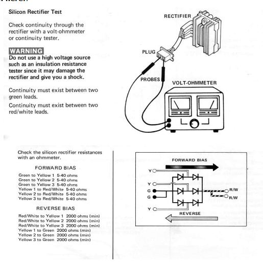
A rectifier is an electrical device that converts alternating current (AC) to direct current (DC) through the use of diodes. Diodes are passive semiconductors that allow current to flow in one direction only. They can be tested with a diode tester or Ohmmeter. A three-phase generator requires six diodes to make DC. There are cheaper ones with only three diodes, but these are not used in GoldWings.
Test the rectifier diodes as shown here:
Regulator theory:
The more load you put on a generator, the more its output voltage collapses. Honda engineers put a variable load in the shape of a regulator on one coil of the stator. This regulator shunts current to the ground, thus simulating heavy load. If all lights are off, battery full and the engine revs at 8000 RPMs, the shunted current is maximal. All lights on, empty battery and engine idling, it is minimal.
In my eyes, it is not the best solution to regulate a voltage, but for sure it works. Negative aspects are: The alternator always is under full load. High currents produce heat and stress to electronic components. Fuel efficiency is slightly decreased. The future will bring better regulator units.
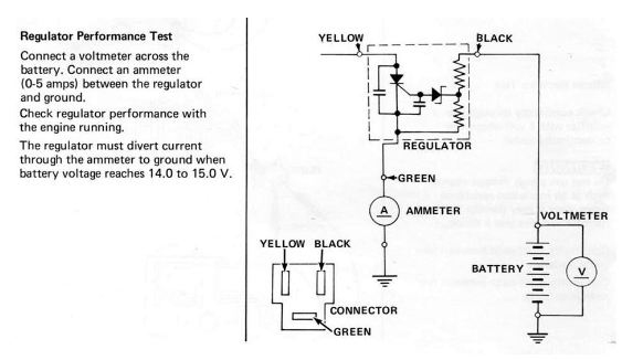
Testing the Regulator:
Additional information:
- The ground wires in the harness are green. Make sure there are no loose connectors between wires and good ground terminals everywhere. Discolored connectors (brown or black) or corroded connector metal is an indicator for a bad connection. Sometimes connectors cannot be properly repaired, cut them off and solder new connectors to the ends.
- If a connector isn’t pulled often, you can also eliminate it by soldering the wires together. This is often recommended for the 3-wire stator connector if it has been overheated, distorted or badly oxidized.
- Connection terminals can be coated with a smear of dielectric grease to retard oxidation.
- Replacing a failed stator, unfortunately, requires engine removal.
Ray Proebstl – Munich, Bavaria, South Germany
email Ray at: monaco2012@gmx.de
If you want to find the best selection online for motorcycle parts, visit our stores below:
www.DimeCityCycles.com | www.Z1Enterprises.com | www.Randakks.com | www.MikesXS.net



Good afternoon. I have a ’76 GL1000 w a single VW carb The carb grounding wire is in an exposed location. Where is the best place to re-locate the carb grounding wire?
Hello! Since I had to replace the battery I went for an AGM, so I checked the charging and it was 15.2 and sometimes more, the max voltage for AGM is 14.9. I did some digging and bought an used FH020AA mosfet regulator mounted in newer models. It only needed making a simple mounting plate and fits in place of the stock rectifier. The connectors where easy to buy so I manufactured an adapter for the 8-pin stock connector. The last step was to drop the original regulator. There is a lot info online about advantages of mosfet regulators. Henryk from Poland
Hi, I am in the process of restoring a 1979 GL1000 that was lying up for some time and was partially stripped, I notice the connector block from the alternator to the main loom has partially melted at some stage, I was going to hard wire this temporarily until I get to a point that I can decide if I need to do a total rebuild or not, as all 3 wires are yellow does it matter in which order they are joined? I did have the motor running briefly for the first time and noticed the output to the battery was heading towards 18 volts but knocked it off quickly.
There is not a comment on KEN MAGUIREs question. Does it matter which of the three yallow wires from the altenator where they go. My plug was melted and my wire marking tape fell off.
I have a charging question on my 77gl1000. The bike at idle or at 3000+ only charges 12-12.5 volts. I have replaced the regulator rectifier with one I have bought threw here. After replacing I still have the same issue. The bike always starts and I have rode it 4-5 hours at a time with no issues but kinda notice my lights are not as bright as they used to be. I tested the windings I found A-B .8, A-C. 8 and B-C .7 and had no resistance to ground. Would this indicate a magnet issue? Also I have a brand new battery.
Thanks, Michael
I have a 78 gl 1000 im getting off and on spark at the points when trying to start it. On side will spark then it dont and the other side will start to spark on and off . i cant seem to find a short any where but.could a.week. battery cause this?
Possible, but not likely. DYNA/S or breaker points ignition?
Hi Randakk,
I have installed your “upgraded” stator during my GL1000 restoration. I have quite low nominal load (led bulbs etc.). My whole electrical system has been replaced including the reg/rec. I’m struggling with very hot wires to from/to the stator. I have the stock connector fitted, but it get so hot that it starts to smoke a little when the battery is fully charged and all the excess load gets shunted. I was going to solder the wires to eliminate the connector and hope that this will fix the issue. Any other ideas?
Brgrds
Karsten Bojesen
Your OEM connector block has failed. Very common. This most expedient fix is to eliminator the connector altogether via hard-wired connection. Or, you can replace the old portion of the connector block with a new replacement block and terminals from Vintage Connections: http://vintageconnections.com
battery issue
many thanks for your advise GREAT new battery and LIFE in the old girl again
THANKYOU!
Glad you got it sorted out.
many thanks, looks like i’ll need another battery, just over a year old this one but only done 60 miles since fitting it…. thanks again
i have an issue with my battery charging when the bike is running but once i turn the bike off i can see the battery voltage go down sometimes below 10v and not able to turn the engine over to start, could this indicate the battery is in need of replacement?
great site
Yes. That is a likely possibility. You should always use a battery maintainer when the bike is parked.
Thank you for maintaining this excellent site, and for offering such a good selection of rebuild kits and accessories. I am nearing the completion of my “refurbishment” of a 1977 GL1000, and am attending to issues that were a bit lower on the list of priorities. I have installed a voltmeter on the handlebars of the bike, and ran the wiring to the positive and negative terminals of the battery. I note that the voltage stays at between 15.0 and 15.4 volts, when the engine is at speed (3,000 rpms and above). The voltage never goes above 15.4 volts. I have performed the tests on the stator and rectifier as described above, and they test “good”. I have replaced the regulator with a salvaged one, and the values are unchanged. The description provided by Ray ( Thank you, Ray! ), leads me to believe that the voltage is (indirectly) reduced by shunting current from the stator to ground. In the diagram above, the green wire from the regulator is shown going directly to ground. In the wiring schematic provided by Sidecar Bob ( Thank you, Bob!) on the NGW site, the ground current takes a much more circuitous route, to the rear Left Turn signal (and connects to the green ground wires going to the rectifier). As the information provided in this post says that the voltage should never go above 15V, I am wondering if I should experiment by providing a direct ground to the regulator, rather than depending on the wiring through the rear left turn signal. Will this damage the rectifier? P.S. the electrolyte levels in the battery appear to be stable (They don’t appear to be boiling off). The voltmeter shows 13.6V at the end of a ride.
Thanks, Ken
Those values seem fine enough probably. It would be worth checking the accuracy of your voltmeter. You can always benefit from a “perfect” ground circuit. Be sure to check the condition of the main ground connection from the battery to the frame. You might want to run your questions by noted Honda expert Mike Nixon: carbrebuilder@gmail.com Good luck. Randakk
The regulator relies on the system voltage on the black sensing wire to determine battery voltage. In a perfect world, they are the same. But our bikes are old. The connections are dirty, wires are brittle, and too much line loss gives the regulator a low reading. Check the voltage supplied to the regulator. You will most likely find it a volt or two lower than battery voltage. It thinks the battery needs more, so it overcharges.
Always a possibility given the age of these bikes now. Thanks.
How does one check the voltage supplied to the regulator? My battery has been boiling down (had to refill it twice in the last month) and this sounds like it might be my issue. I need a new battery (drops to 3V when I push the start button), but don’t want to put a new one in there until I know that the cycle won’t repeat itself.
Follow the steps outlined above. There are additional useful procedure / explanation steps in the OEM Honda workshop Manual.
My Lady just made it possible for me to get my hands on a 75 GL,beautiful….gloss black bare wing and I don’t give a good damn how long it takes me to figure out aaaaaalllllllll this tech info on keepin the bike healthy….I won’t give up on the bike Lord help me…..runnin allright for now,think I’ll change out or check the belts,change out the fluids and all and ride that thing to hell and heaven back and forth…
Love the bike and in time all this reading and attempting to tackle projects in maintainence will make me a mechanic in years to come…36 years old,first true street machine owner right here…..thanks to all,Randakk,octane,old fogey,nwclub,goldwing docs….non of this interesting,complex s**t would be happening w?out all of you.
Thanks and good luck on your project.